David Noel
<davidn@aoi.com.au>
Ben Franklin Centre for Theoretical Research
PO Box 27, Subiaco, WA 6008, Australia.
DS911:The Modular AirCube
A basis for all manner of lifting and transporting devices, structures, and edifices
Summary
Attenuated-air devices have a 2000-year history, starting with the Chinese Sky Lantern, a small hot-air balloon. Other such devices perfected or imagined over the years include hydrogen balloons and vacuum balloons, all individual devices, mostly for lifting purposes. The present article describes the construction of all manner of structures and devices, using Modular AirCubes to produce objects of much lower cost and wider application than the conventional one-item approach.
Attenuated-air devices in history
Attenuated-air devices have a history of more than 2000 years, starting with the Chinese Sky Lantern. This is believed to date back to the Third Century BC, but perhaps the oldest well-documented sources are the references to the Chinese sage and military strategist Zhuge Liang (181–234 AD), popularly called Kongming.
Kongming is said to have used a message written on a sky lantern to summon help on an occasion when he was surrounded by enemy troops. For this reason, they are still known in China as Kongming lanterns.
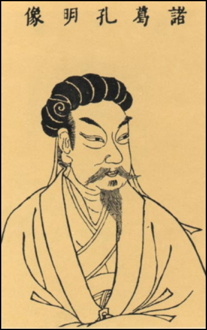
Figure DS911-F1. The Chinese military strategist Kongming.
In modern times, sky lanterns are readily available from the Internet, costing less than $2 each. These miniature hot-air balloons get their lift from a contained lit candle or similar fuel source.
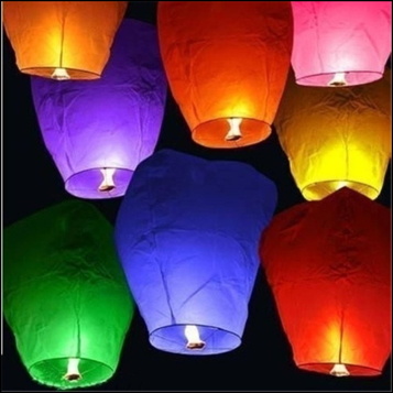
Figure DS911-F2. Sky Lanterns as sold over the Internet. From [1].
In good weather conditions, the fuel in a sky lantern will last 8--10 minutes, enabling it to reach heights of 200--500 metres and travel 3--8 kilometres from the launch site. Because of the fire risk, launching sky lanterns is banned in some jurisdictions.
Passenger-carrying balloons
The first hot-air balloons capable of carrying passengers were developed in France by the Montgolfier Brothers, in 1783 [5]. The first free flight carrying human passengers took place on November 21 in Paris, and among the spectators was Benjamin Franklin, who was the US Ambassador to France at the time.
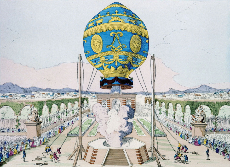
Figure DS911-F3. Launch of a Montgolfier hot-air balloon. From [6].
In modern times, hot-air balloons are mostly used for recreational flights, though some are used in research. These balloons can reach extreme altitudes -- in 2005 one attained a height of over 21 kilometres [5].
Hydrogen-filled passenger balloons were developed at the same time as hot-air balloons. The first manned flight of a hydrogen balloon took place in Paris on December 1, 1783, only a few days after the hot-air balloon launch. The flight reached a height of 550 metres, and went for 36 kilometres [7].
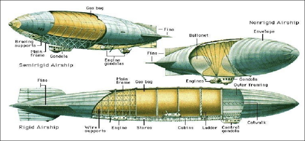
Figure DS911-F4. Construction variations in airships. From [9]..
During the early 1900s, rapid development took place of gas-filled airships, particularly the German craft known as Zeppelins [8]. These airships had a number of gas bags contained within a rigid light metal frame. Between 1910 and 1937, commercial airship services were run using hydrogen-filled Zeppelins. Zeppelins were also used by the German military to bomb Britain during the first World War.
Vacuum balloons
In 1982 I realized that lighter-than-air craft could be made using cells from which all air had been evacuated -- vacuum balloons -- and had an article published in Speculations in Science and Technology [9].
Obviously the evacuated cells had to have rigid enough walls so that they would not collapse under the pressure of the surrounding atmosphere. This could be done with a rigid metal sphere, or with a spherical wall supported by a geodesic dome framework. It could also be done with an inflated double sphere, like an inflated motor tyre, with the two surfaces connected by threads. I consulted with a local mathematician, Malcolm Hood, and his advice was that such a device would theoretically be stable in a 1-atmosphere pressure if the internal pressure of the air within the double skin was in excess of 2 atmospheres.
I had read a story by the science-fiction author and inventor Arthur C Clarke, in which one of the characters claimed that the only lifting balloon possible, on a planet with a hydrogen atmosphere, would be one based on hot hydrogen. I sent a copy of the Speculations article [9] to Clarke, pointing out that a vacuum balloon should also work.
Clarke replied graciously and said the article was very interesting, but why hadn't I mentioned Lana's work? When I followed up Clarke's lead, I was very surprised to find that as long ago as 1670, a Jesuit Monk, Francis Lana, described an aircraft based on the vacuum balloon principle in his book Prodromo dell'Arte Maestra, published in Brescia, Italy.
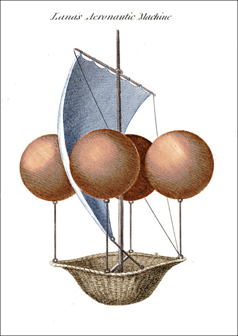
Figure DS911-F5. Lana's Aeronautic Machine. From [12].
Lana's design suggested using perfectly spherical, evacuated thin-copper spheres. In practice, these would have been rapidly crushed by the atmosphere. But the theory is sound, and evacuation, together with attenuation by heating, and part or full replacement by hydrogen, form the three main contenders for use in AirCubes.
In 2006, I collected together various discussions and suggestions about vacuum balloons in a web article, The Vacuum Balloon [11].
The modular principle in AirCubes
Building up devices and structures from standard modules is a basic requirement in the development of AirCubes as practical and commercial items. In this approach, the standard module is taken to be a cube with edge dimensions of 2 metres -- and hence with an internal volume of 8 cubic metres.
The importance of modularity can be seen by comparison with another type of project, that of building a house. In Western Australia, it is still common to build detached houses with double-brick walls (inside and outside walls both brick). A typical house might use 20,000 bricks.
If architects draw up a plan for a house using double-brick walls, they need only specify the dimensions of the walls. Bricks are a standard size, they can be obtained from any brick supplier to suit.
The production of a commercial airship like a Zeppelin is a major project, and involves considerable planning and major costs, typically in the millions of dollars. It is estimated below that Modular AirCubes, produced in a large factory, would cost only $10 each, and perhaps less.
A competent bricklayer could conceivably himself build most of the structure of a brick house, working from a rough plan, and ordering new lots of bricks as needed. Similarly, a competent person could conceivably build many of the devices and structures described below, ordering in batches of AirCubes as needed.
Manufacturing AirCubes
In this article, "AirCube" refers to one module of a system of construction using empty cubes, each made up by joining 6 sides or Faces, usually made of plastic and fibres. Typically, each Face is a double skin with the two sides of the Face connected together by multiple threads, and each face can be made rigid by inflating the air between the two sides.
There is an existing heavier analog of AirCube faces which uses "Drop-Stitch Fabric", a special type of PVC-coated fabric material that has billions of polyester "spacer threads" holding the top and bottom PVC layers. The air chamber is held firmly in shape by these spacer threads, allowing the inflated structure to maintain its shape and stability under heavy outside pressure and impact. These fabrics are used to produce inflatable boats and docks, some of considerable size -- as much as 18 metres long.
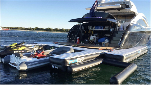
Figure DS911-F6. Inflated boat and dock structures. From [13].
For AirCube faces, the structures must be much lighter than those using drop-stitch fabrics. Each square face has sides of length 2 metres, so when six Faces are combined into a cube, this cube will have a volume of 8 cubic metres.
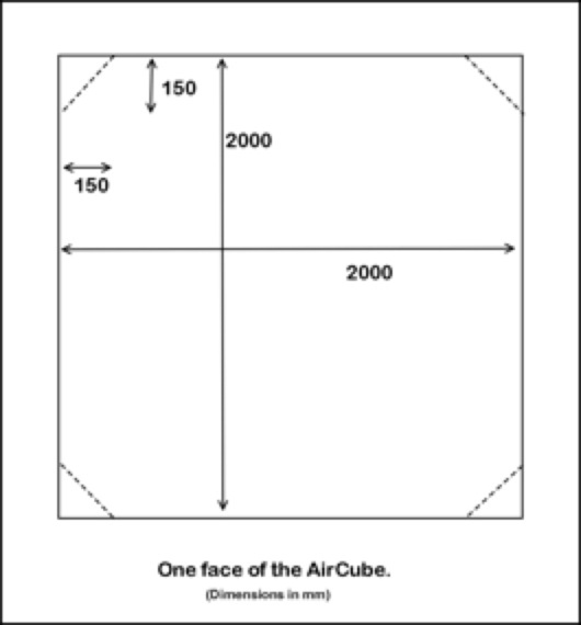
Figure DS911-F7. An AirCube face.
Note that the corners of each Face in Figure 7 are shown as separate parts (with dotted lines). In the process of joining the six Faces to make a cube, these corners are folded back and not joined to adjacent Faces. The reasons for this will be seen below.
Typically each Face is a square made up of two PVC layers, enclosing a square of fibre fluff slightly smaller than the enclosing PVC layers.
Pilot Manufacture of AirCube Faces
Setting up a manufacturing facility for producing AirCube Faces will first require trials of suitable materials. The three components to be trialled are: the Sheeting, the Fibre, and the Adhesive. A suggested trial route is described in Appendix 1: Pilot Manufacture of AirCube Faces.
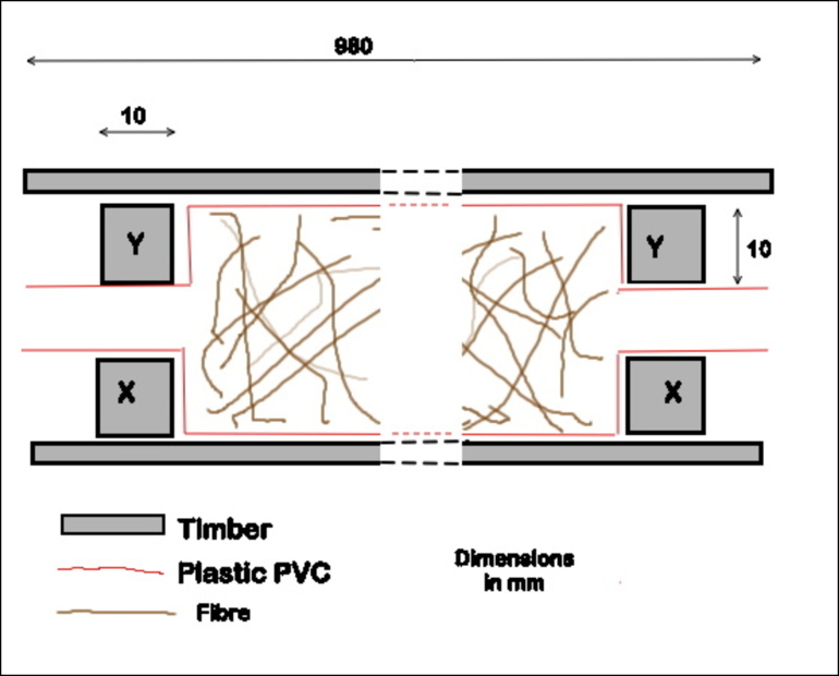
Figure DS911-F8. Pilot production of AirCube faces.
Initially, the Sheeting is likely to be some form of flexible sheet plastic. The Fibre could be a natural fibre such as sisal, or a synthetic one such as carbon fibre, and the Adhesive could be an epoxy glue. The aim would be to produce Faces which would be as rigid as possible when inflated, consistent with minimum weight.
Manufacture and assembly of Simple AirCubes
AirCube faces would typically be manufactured in a continuous belt, as depicted in Figure 9. The brown parts are where fibres fill the space between the Sheeting, while the white parts are where both parts of the Sheeting are welded together,
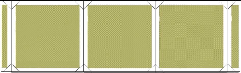
Figure DS911-F9. Factory production of Simple AirCube Face belts.
A cube has 6 faces. To put together an AirCube, six faces are cut from the belt, in two sets of 3. Each triplet is bent at the joint into an open U-shape, as in Figure 10. The two triplets are put together to form the six faces of the cube. This arrangement means that half the face-edge joins are already made.
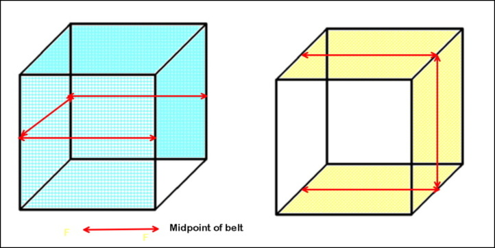
Figure DS911-F10. Two face-triplets joined to form a complete cube.
The rest of the joins are then made by heat-pressing, glueing, or some other means (such as with ultraviolet-set resin). Note that the cube corners are not square, as shown in Figure 10. Instead, the belt sections are cut down to where the dotted lines intersect in Figure 9, leaving triangular flaps. These flaps are then glued together so that all corners of the cube are bevelled. If, in making the bevelled corners, one or more tabs are formed, these provide the simplest means of combining a number of cubes, by roping them together.
In an alternative simple method of assembly, use is made of the sort of press seals used to open or close plastic bags. During manufacture of the Face belts, these press seals are incorporated along the belt sides and between each face. To assemble an AirCube, the edges of the six Faces are simply pressed together.
For transport, Faces can be folded back on each other to form a vertical stack, as in Figure 11. This pattern is technically known as a boustrophedon pattern.
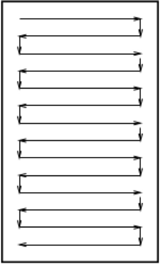
Figure DS911-F11. Stacking Face belts for transport in boustrophedon pattern.
AirCube contents and lifting ability
Once formed, a cube has one internal space (the Core) and six bounding faces, each of which has an internal (Skin) space. The contents of each of these spaces will be referred to as the Core Fluids and the Skin Fluids. Typically, the Core Fluid will be hydrogen or attenuated air, and the Skin Fluid will be compressed air.
The simplest approach is to use hot air as the Core Fluid, but hydrogen and attenuation by pumping can be used without any special problems. The most lift will be obtained when the Core Fluid is completely attenuated, that is, is a vacuum, but lesser degrees of attenuation have been demonstrated successfully in the past, in particular, with hot-air balloons.
Figure 12 shows a table of air density at different temperatures.
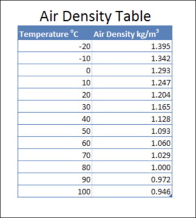
Figure DS911-F12. Air density at different temperatures. From [14].
At a standard temperature of 20 deg C ("room temperature"), 1 cubic metre of air weighs about 1.2 Kg. Displacing this air with a complete vacuum would yield a theoretical lift of the same amount, 1.2 Kg. A standard AirCube would have a volume of 8 cubic metres, and a theoretical lift of 9.6 Kg. For convenience of calculation, assume that the structure of the AirCube weighs 1.6 Kg, then the "standard lift" of an evacuated AirCube would be 8 Kilograms.
We will use this "Standard Lift" of an AirCube of 8 kg in the various calculations below. It should certainly be attainable, possibly even bettered, but that depends on details of materials and such.
Now consider the AirCube as a hot-air balloon. Note from the table in Figure 12, that 1 cubic metre of air at a temperature of 80 deg C (a reasonable working temperature) has a density of about 1.0 Kg per cubic metre (about 83% of a standard atmospheric). Therefore, heating the air inside an AirCube to 80 deg C should provide a lift of 0.2 x 8 Kg = 1.6 Kg -- just about enough for the AirCube to start to take off.
As a simple trial, an electric element could be inserted inside an AirCube to heat the air inside to 80 deg C, with an escape valve to allow excess air to escape. If this air increased in temperature above 80 deg C, the AirCube should start to rise -- and there would be no pressure difference between the outside and the inside of the cube.
The same reasoning applies if a vacuum pump was applied to suck some of the air out of the AirCube. When the Core Fluid is attenuated to about 83% of standard, the AirCube should start to rise, There is no need to evacuate the air completely to demonstrate the effect.
For comparison, if all the air in an AirCube was replaced by hydrogen, this would reduce the density of the Core contents to about 7% of standard, providing considerable lift. Heating the hydrogen would increase the lift.
For practical use, photocells on the surface of an AirCube could provide ample power to heat the air inside -- the candle in a Sky Lantern represents about 80 Watts of power. For night-time use, a rechargeable battery could be added, though this might not be needed (once heated, air inside an AirCube should be insulated by the still-air Sides, as are double-glazed windows).
Manufacture and assembly of Complex AirCubes
The properties and capabilities of simple AirCubes could be greatly enhanced by a number of improvements at both the manufacturing and assembly stages.
Corner Sockets. It was mentioned earlier that AirCubes would not have square corners, instead the corners would be bevelled (in Figure 7, the Face corners are shown with dotted folds at 150 mm from the square corners). Figure 13 shows a schematic of AirCube corners.
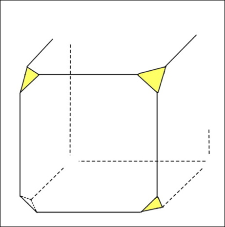
Figure DS911-F13. Bevelled corners of AirCube.
While, in the Simple AirCube, these bevelled corners might have one or more tags or loops (through which cords could be used to tie groups of AirCubes together), in the next stage, Corner Sockets would be inserted in all corners. These would consist of short lengths of rigid tubing, with a plug or valve at the centre to close off the Socket.
Internal Struts. In the next stage, Struts could be used to improve the rigidity of the Cube and strengthen it against collapse. In their simplest form, Struts would be hollow plastic tubes, but much variation is possible, as with carbon-fibre tubes, or tubes with many holes in their sides, or with internal pin supports (as in some bird bones). When an AirCube assembly includes Struts, they can be collectively classed as the assembly's Endo-Skeleton.
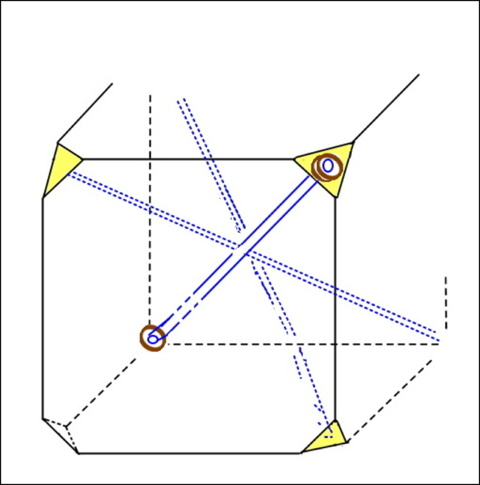
Figure DS911-F14. Cube with Sockets and Struts.
If used, Struts would fit into the inside part of the Sockets. There would be 4 Struts in each Cube, crossing at the centre of the Cube, where they would be tied together. They would greatly strengthen the Cube against collapse.
Nodes. An assembly of 8 Cubes (2 x 2 x 2) would have at its centre a space in the shape of a regular octahedron (with 8 triangular faces, each matching the bevelled corner of one of the enclosing Cubes). In another development, this space could contain an octahedral Node.
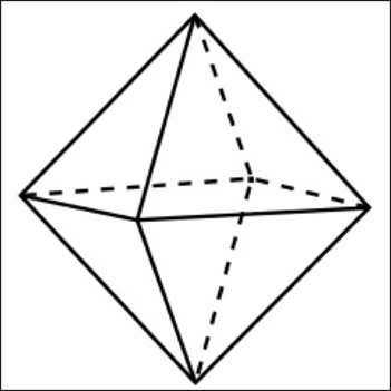
Figure DS911-F15. The octahedral Node.
In multi-Cube assemblies, the Nodes would play a vital part in controlling the behaviour of the assembly, In their simplest role, each face of the Node would contain a plug which would fit into the outside part of the Socket, so Cubes could be assembled together like Lego blocks. The plug/socket joins could be separable or permanently fused, according to need.
External Struts. For an assembly of Cubes which needed to be rigid, independently of their contents, external Struts could be added, connecting together the Nodes. For such assemblies, the external Struts would form their Exo-Skeleton. For very large assemblies, the Exo-Skeleton might be needed for attachment to the various loads.
The Selvedge. In the most developed form of manufacturing, for the Complex AirCube, extra line items would be inserted along the edges of the Face belts during the manufacturing process.
Figure 16 shows a section of the Face belt as supplied by the Belt manufacturer. Along one edge of the belt (the Selvedge) three line services (A, B, C) are built in, and the outer edge (E1) is also formed in a special way.
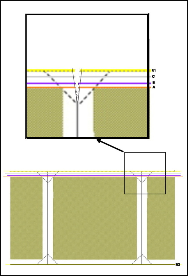
Figure DS911-F16. Line services in the Selvedge.
Two of the line services are thin (maybe 2 mm) plastic tubes, the other is a wire as used in a computer USB connector. The concept is that the line services are available, if required, to increase the capability of an assembly of AirCubes. During the manufacturing process, the line services are cut across and sealed at the intersections of the Faces. The outer edge (E1) is formed as the male part of a seal as in a zip-seal plastic bag, while the edge on the other side of the belt (E2) is formed as the female part of the zip-seal.
The aim of all this is to make it possible to use a standard modular product from a manufacturer (the Face-belt) and customize it for a particular assembly to produce an "intelligent" assembly by connecting the line services, as required, to the Node which is positioned between the Cubes. Any of the line services can be stripped back towards the dotted fold, joiners added (USB connectors for the wire), and these plugged into sockets in the (customized) Node.
The final outcome of the process should yield an AirCube assembly through which the Core Fluids and Skin Fluids can be pumped in or out through program circuitry present in the Complex Nodes.
The aim is that the manufacturer should supply a single product, produced on a continuous assembly line in an automated plant, in the form of a long, rolled-up or folded belt, and that this product should be customized as required. This might be at the manufacturer's supply centres, or advanced users' own premises.
It is estimated that material costs for a standard modular AirCube could be as little as $10, for a sufficiently large market.
Manufacture and assembly of Complex AirCubes
The range of items which might be produced from AirCubes or AirCube assemblies is very large. Some suggestions are outlined here.
The Cube-Drone. The Cube-Drone would use a single AirCube, or possibly a pair, to function like the helicopter-style drones which are coming into use for aerial photography, searches, and delivery of small articles. The Cube-Drones would have an advantage over the normal drones in that they would not need energy to stay afloat, although they would need motor energy to follow a prescribed path. They would not work well under very windy conditions.
Cube-Drones could also function in mineral prospecting. Because they would not use energy to stay aloft, they could be programmed to prospect quite a big area over several hours, using magnetometers, metal-detectors or similar, and radioing their readings back to a base point as they did so. They could also function at night, recording ground emissions at infrared or other wavelengths which would be drowned out by sunlight during the day.
The Cube-Tether. Devices similar to Cube-Drones, but tethered to the ground (or a ship) could be used where continuous actions needed to taken, at height, over semi-permanent stretches of time. These actions could be weather reporting, transmitting or receiving cell-phone signals, and detecting distant ships or planes "over the horizon". Their heights in the sky are more likely to be limited by legislation, rather than by technical limitations.
In a simple application, an AirCube with an electric element inside, powered through the tether, could be used as a Cube-Tether -- technology involving neither hydrogen nor vacuum for lift.
The Cube-Medusa. Large tethered structures kept afloat by hydrogen at a height of about 1 kilometre were described in a 2011 web article, with the title "The Hydro Medusa". This article had the subtitle "Free water, energy, fuel, and communications anywhere on Earth". Such devices could be implemented using standard AirCubes.
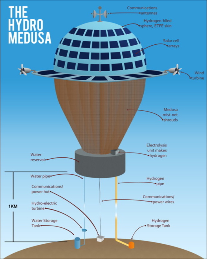
Figure DS911-F17. The Hydro-Medusa. From [15].
According to this article [15], "Almost everywhere on the Earth's surface has an adequate supply of free water and energy within 10 kilometres! Unbelievable as this may seem, this article shows how this may be brought about". In the initial concept plan, the Medusa is maintained at a height of about 1 kilometre above the ground. At this height, it would be an excellent communications structure for television broadcasting transmitters and mobile phone repeater towers.
The Medusa could gather and condense water from mist nets or condensation panels, mimicking techniques used by plants (and even insects) in arid regions [16]. It could also gather power from photo-cell arrays, wind turbines, and hydro-electric turbines (water falling through a head of 1000 metres). Some of the power could be used to electrolyse some of the water to produce hydrogen for lift, or as a fuel.
Cube-Rafts. Cube-Drones and Cube-Tethers would use small numbers of AirCubes. Because of their modular nature, and likely small unit cost, it would be quite feasible and economic to use larger assemblies of the Cubes for lifting and freighting purposes.
For example, assuming a standard unit lifting power of 8 Kg, an AirCube assembly of 4 x 4 x 16 (256) units would have a lifting power of 256 x 8 Kg -- about 2 tonnes. Such an assembly, within a suitable frame, cover, or superstructure, could be called a Cube-Raft.
A raft platform with a lifting power of 2 tonnes would be useful for a range of local and regional uses. These might include moving goods within a community, carrying parts of a building being constructed to a required height (Cube-Cranes), and freighting small containers to distant destinations, over land or sea. It might prove more usual not to provide propellors on the CubeRafts themselves, but instead to add in the required sets of Cube-Tugs -- special Air-Cube assemblies fitted with motors (diesel, hydrogen-fuel-cell, etc) for particular needs.
Cube-Rafts could also be crew-less, controlled by software like driver-less cars, or could be remotely controlled like the giant ore trucks and ore trains in Western Australia. Small Cube-Rafts might be tethered to a truck, which might pick up a building component at the manufacturing site, attached to a Raft, drive to the building site with the Raft floating 20 metres overhead, and on arrival let out the tether to raise the component 100 metres to the current build position.
As a basis for calculation, assume an AirCube assembly of 256 units has a lifting capacity of 2 tonnes. With a unit cost of $10, the whole raft would cost $2560. Obviously control and superstructure costs would need to be added to this, but it is feasible that a complete, off-the-shelf 2-tonne Cube-Raft could be sold for $5000.
Cube-Freighters. Cube-Freighters are much larger AirCube rafts or raft sets, capable of carrying international air-freight cargo. An air-freight company such as DHL uses freighter versions of aircraft such as the Boeing 757 [17]. Such an aircraft could cost 30-50 million dollars, carry a cargo of 35 tonnes, and cost 3 million dollars a year to run.
Say you would like a Cube-Freighter capable of carrying 40 tonnes, comparable to a Boeing 757. Put together 20 Cube-Rafts, each costing $5000, total cost is 0.1 million dollars. Double this cost to include framing and propulsion, say $200,000. This for a craft not needing an airport or dock, capable of travel over land or sea.
The Cube-Stalk. Cube-Stalks or square towers could be put together from assembled AirCubes to form structures of any desired height. Because each level of the Stalk would be self-supporting, the Tower could be easily assembled at ground level. The procedure might be: tethering construction to date, letting that rise one level (2 metres), adding in a new level of AirCubes, and so on.
Cube-Stalks could have similar functions to the tethered Cube-Medusas described above. The could also as the support points for giant nets or canopies, maybe 1 kilometre on a side, which in one application could carry photocells to produce electricity or hydrogen to be piped to the ground.
Cube-Solar-Towers. Solar Towers for electricity generation include two main components, the greenhouse and the tower. The greenhouse has a very large inverted-saucer transparent canopy for collection of sunlight and solar heat (infrared) during the day, with a bed of dark rocks or other material to store heat to use during the night (Figure 18).
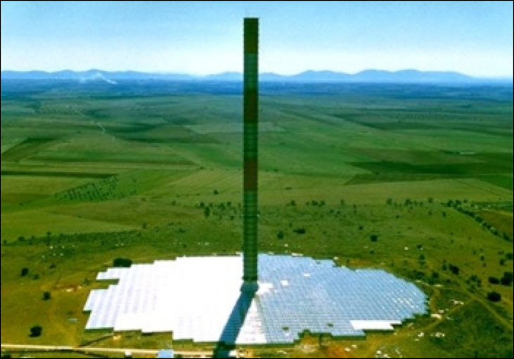
Figure DS911-F18. Working Solar Tower. From [18].
Heat collected under the greenhouse rises up and into a central tower, where the upflow drives one or more conventional turbines.
Solar Tower technology has been tested and proven with a successful small-scale pilot plant constructed in Manzanares, Spain [18]. The pilot project was the result of collaboration between the Spanish Government and the German designers, Schlaich Bergermann and Partner. The plant operated for seven years between 1982 and 1989, and consistently generated 50kW output of green energy.
The pilot plant conclusively proved that the concept works, and provided data for design modifications to achieve greater commercial and economic benefits associated with an increased economy of scale. The pilot plant was taken out of use only because its steel support cables rusted. The design principles had been verified. In an interesting side note, it was found that fruiting trees grew very well in the warm rapid airflows under the solar tower canopy.
Both the greenhouse and the tower could easily be constructed from AirCubes. and being self-supporting, would not need support cables. Cube-Solar-Towers would even be demountable, able to be shifted to a new area of demand.
Cube-Windcatchers. The Norwegian company WCS (Wind Catching Systems) has released its design for a colossal floating wind turbine array, which it says can generate five times the annual energy of the world's biggest single turbines. This while reducing costs enough to be immediately competitive with grid prices [20].
Standing more than 324 m high, these mammoth Windcatcher grids would deploy multiple smaller turbines in a staggered formation atop a floating platform, moored to the ocean floor using oil and gas industry techniques.
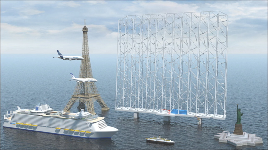
Figure DS911-F19. Windcatcher Grid, with other comparable-size objects. From [20].
The multiple smaller rotors could perform much better in wind speeds over 40 to 43 km/h, when larger turbines tend to start pitching their blades to limit production and protect themselves from damage. The overall effect, says WCS, is a 500% boost in annual energy output, with each array making enough power to run 80,000 European homes.
A Windcatcher system using AirCubes would be much simpler and cheaper than the Norwegian plan. Instead of a flat grid, Cube-Windcatchers could be set up in the form of windsocks, with hundreds of turbines lining the surfaces of the windsocks. Secured by cables above an industrial area, fields of windsock-shaped Cube-Windcatchers could supply all the power needed by the industrial precinct -- as long as the wind blew.
Cube-Launchers for Space Freight. Because each level of a Cube-Stalk would be self-supporting, the Stalk could be extended upwards more or less indefinitely, certainly to the current record for a high-altitude balloon, 53 kilometres. Using special Air-Cubes for the upper levels, perhaps with hydrogen as the Skin Fluid and vacuum for the Core Fluid, this record might conceivably be beaten.
A hollow Cube-Stalk could be used to launch items into space, using thin metal tracks and linear-motor principles, possibly even using photocells on its outer surface to supply the necessary energy -- free space-travel. A sophisticated Cube-Launcher could even change its shape in its upper reaches, to direct a payload into a particular orientation in space.
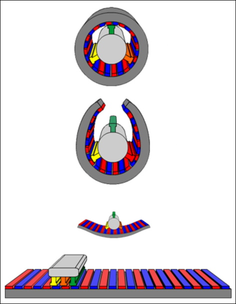
Figure DS911-F20. Synchronous linear motor. From [19].
In linear-motor designs the rate of movement of the magnetic field is controlled, usually electronically, to track the motion of the rotor. Synchronous linear motors rarely use commutators, so the rotor often contains permanent magnets, or soft iron. Examples of linear motors include rail-guns and the motors used on maglev systems [19].
The Cube-House. Habitable structures could be erected very quickly and easily using AirCubes for the outer walls and roof. Such structures could also be used as temporary tents, enclosing a building under construction to exclude detrimental weather effects. In such structures, the lower-level AirCubes could contain water as part of their Core Fluid, giving them a solid anchorage.
In more permanent structures, the ground-level AirCubes could be pumped with concrete or another solidifying material.
Because such structures would have self-supporting roofs, they could easily be made very large, maybe as aircraft or spacecraft hangars. They could also be used as warehouses or to store grain, or enclose communities -- the "domed-cities" of science fiction.
Cube-Strata and Cube-Fields. The possibility was mentioned above of Cube-Stalks supporting nets or canopies -- large flat surfaces to carry photocells or other services. It would be possible to "super-size" these nets into enormous rafts, of kilometre dimensions, with beds several Cube thicknesses, capable of carrying heavier loads.
These Cube-Strata might carry such industries as automated hydroponic plant production -- floating at heights where light and water vapour were abundant, these Strata Greenhouses could be very productive.
Agriculture and horticulture could be well suited to Cube-Strata. Conventional farmers always need to consider the costs and bad effects of insect pests. These could be easily avoided by moving the growing strata a few hundred metres into the air, away from the conditions hosting the pests. Strata could be moved to temporarily to adjacent spots with more favourable conditions, harvested in the air, or lowered to the ground for major overhauls.
Cube-Strata need not necessarily shade inhabited areas, they could float above areas of sea or desert. They could possibly even support human habitation -- "Check the news centre, they're moving our Stratum next week into a more temperate weather band for the Summer".
Cube-Viaducts and Cube-Interways
There are considerable developments possible using long, continuous, Air-Cube structures which link population or activity centres and carry materials, communication services, and perhaps eventually, people.
Cube-Viaducts. A concept sketch for Cube-Viaducts is shown in Figure 21. The intention is to build floating "roadways" or viaducts, connecting together locations and carrying services or materials.
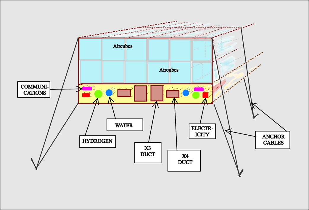
Figure DS911-F21. Concept sketch for AirCube Viaducts and Glideways.
Cube-Viaducts could extend over land or water. They could carry pipelines containing water, hydrogen or other gases, and communications cables, also electrical cables. They could be linked internationally. They might well gather much of their energy from photovoltaics.
Obviously any implementations would need protection from weather events. Net covers would be standard. Strong winds could be catered for, cyclones and tornados would be risk factors, as in normal constructions.
Cube-Interways. An important use of Cube-Viaducts would be as Cube-Interways, networks for carrying goods and packages.
In the modern world, transmission of information and information-based media has been revolutionized by the use of computers and the Internet. Nowadays, users in their own home can get a movie delivered to their TV or computer with a simple command. The transaction may be in real time, and involve no human action apart from that of the user themselves.
Cube-Interways could be planned to provide transmission of goods or packages with the same human-free facility as for information. In Figure 21, the suggested Cube-Interways are shown as ducts, X3 and X4 Ducts.
The nature of these ducts is only notional at this stage. Rather than being of solid material as in air-conditioning ducts, they might be open frameworks of netting material, meant to catch accidental falls.
Goods would be moved along the duct Interways using "Baskets", frames equipped with linear motors, moving on tracks either above or below the "Baskets" -- rectangular containers, again of notional design.
It could useful to design the Baskets to be in Golden Cuboid shapes -- cuboids where the longest edges are the square root of 2 longer than the medium edges, which are the square root of 2 longer than the shorter edges [21].
In Figure 21, it is suggested that the Interway section depicted holds X3 and X4 Ducts. These would be of a size to carry Baskets in the X0 range of golden cuboid sizes (Figure 22).
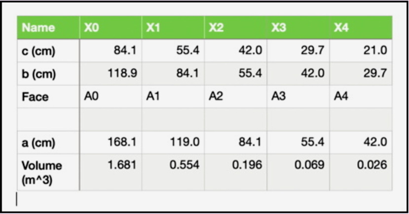
Figure DS911-F22. The X-Series range of Golden Cuboids, From [21].
In this range of cuboids, the Endpoint is set by making the smaller face of each cuboid equal to the corresponding paper size in the A0 series of metric paper sizes [21]. So the X3 and X4 ducts in Figure 21 would carry Baskets with sides equal to A3 and A4 paper sizes.
Using the Golden Cuboid system means that Baskets can be switched between adjacent-size ducts, so that an X3 duct could carry an X4 basket turned through 90 degrees. Also, Baskets could sometimes be nestable, with a set of smaller baskets clamped together forming a cluster the same size as one higher in the range,
Baskets would all carry computer chips in their frames, capable of storing the intended address of a particular journey, plus other information which might be needed, such as for Customs checks. They would also have automatically-contacting data connections on all sides, so that the carrier ducts would have real-time availability of all relevant information concerning the baskets and basket-clusters they were conveying.
Ultimately, the system could be developed to the stage where it was effectively an Internet of Goods. A manufacturer of, say, spare parts for vehicles could conceivably use their order-fulfilment system to automatically write the electronic address of a customer package on a basket-chip, and automatically place the basket in an Interway Gate on their own premises.
The Interway system envisaged could evolve to cover the planet, with Interway streams passing through Way-stations where baskets and basket clusters were separated and combined and directed along relevant routes, without human intervention. Where inter-continental or long-distance sections were involved, baskets could be moved into Interway Holds fitted into ships or airplanes, to be discharged into local nodes of the Interway in their destination countries -- again without human intervention.
Air-Cube Materials
While it has been suggested that standard Air-Cubes might be of uniform construction and materials, specialist lines could be manufactured for particular purposes. Traditional drop-stitch fabrics use PVC as the skin-forming plastic. There are plenty of other possibilities for particular purposes, such the tough and impermeable plastic EFTE (ethylene tetrafluoroethylene), used in building the Water Cube swimming centre for the Beijing Olympic Games [22]. Silicone materials, known for their resistance to heat, are also possibilities. Plastics with reflective surfaces could be useful for heat retention.
Skins containing carbon fibres, graphenes, or the recently discovered HBNs (hexagonal boron nitrides) [23] offer possibilities for extreme toughness combined with light weight.
The AirCube as the analog of living creature cells
The largest living creature on Earth is said to be the Great Barrier Reef off the east coast of Australia. It is essentially made up of cells -- animal, vegetable, and fungal, living and dead. The Reef, and almost everything we think of as life, is a conglomeration of cells.
Some of Nature's most intriguing creatures go under the unattractive name of Slime Moulds. For most of their lives, these are single-celled creatures like amoebas, living in isolation.
Yet when under stress, these slime moulds can do amazing things -- they can combine together to form slug-like bodies or "grexes" which can move relatively quickly across a landscape. They can also come together to form fruiting bodies, which release spores into the air.
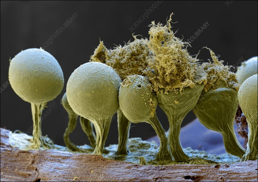
Figure DS911-F23. Slime Mould fruiting bodies, From [25].
In [24] it says "When food is abundant, these slime molds exist as single-celled organisms. When food is in short supply, many of these single-celled organisms will congregate and start moving as a single body. In this state they are sensitive to airborne chemicals and can detect food sources. They can readily change the shape and function of parts, and may form stalks that produce fruiting bodies, releasing countless spores, light enough to be carried on the wind or hitch a ride on passing animals".
In their combined form, Slime Moulds have been claimed to be capable of many of the functions usually ascribed to complex animals, such as solving maze puzzles!
In a similar way, there is the possibility for some of the complex things we use in civilization being developed through combining AirCube Modules. In this, the Module is the industrial equivalent of the Cell. The Endo-Skeleton and Exo-Skeleton are analogs of mammalian skeletons and turtle shells, Nodes are the analogs of neurones and nerve cell junctions, the Selvedge services are the analogs of lymphatic, endocrine, and nerve systems. With increasing development of the Nodes, an AirCube assembly begins to take on some aspects of intelligence.
In this analogy, the standard Air-Cube is the equivalent of a stem-cell, convertible by choice and design into a specialist bone, skin, blood, liver, or other cell. Air-Cubes could be a useful step in the progress of civilization.
Conclusion
This article is intended to alert the World to a vast range of possible uses for devices and structures based on attenuated-air modules. It is offered in a spirit of humility, for others to develop possible devices and ideas in the future.
* * * * * * * * * * * * * * * * * *
References and Links
[1]. Wish Chinese Paper Lanterns Sky Fire Fly. https://www.wish.com/product/5d01eb4e8093636dd3ec64fc .
[2]. Sky Lantern. https://en.wikipedia.org/wiki/Sky_lantern
[3]. Zhuge Liang. https://en.wikipedia.org/wiki/File:Zhuge_Liang_scth.jpg .
[4]. Common Questions About Sky Lanterns. https://weddingdaysparklers.com/common-questions-about-sky-lanterns/ .
[5]. Hot-air balloon. https://en.wikipedia.org/wiki/Hot-air_balloon .
[6]. Joseph-Michel and Jacques-Étienne Montgolfier. https://www.britannica.com/biography/Montgolfier-brothers .
[7]. History of ballooning. https://en.wikipedia.org/wiki/History_of_ballooning.
[8]. Zeppelin. https://en.wikipedia.org/wiki/Zeppelin.
[9]. A Brief Study on Airship Using Aerospace, Electronic and Communication Applications. Md Abdul Sami et al. Int. Journal of Engineering Research and Applications, Vol. 5, April 2015, pp.34-46. Online: http://ijera.com/papers/Vol5_issue4/Part%20-%205/G504053446.pdf .
[10]. David Noel. Speculations in Science and Technology, Vol. 6, No. 3, 1983, p. 262-267. Online: http://aoi.com.au/Originals/VacuumBalloon.pdf .
[11]. David Noel. The Vacuum Balloon. http://aoi.com.au/bcw/VacuumBalloon.htm. 2006.
[12]. Lana's Aeronautic Machine. https://www.sciencephoto.com/media/1004316/view/lana-s-aeronautic-machine-illustration .
[13]. Zephyr Yachting. https://www.zephyr-yachting.com/luxury-watertoys/zephyr-inflatables/funair-inflatables/funair-personal-watercraft-docks/.
[14]. How Hot Air Balloons Fly. https://www.brisbanehotairballooning.com.au/how-hot-air-balloons-fly/.
[15]. David Noel. The Hydro Medusa: Free water, energy, fuel, and communications anywhere on Earth. http://aoi.com.au/devices/Hydro-Medusa/index.htm .
[16]. David Noel. LB702: How plants water themselves from the air. http://aoi.com.au/LB/LB702/ .
[17]. Boeing 757. https://en.wikipedia.org/wiki/Boeing_757.
[18]. Solar Updraft Towers Generate Mega Power. http://www.solaripedia.com/13/371/5042/solar_updraft_tower_pilot_plant.html .
[19]. Linear motor. https://en.wikipedia.org/wiki/Linear_motor .
[20]. Loz Blain. 1,000-foot multi-rotor floating Windcatchers to power 80,000 homes each. https://newatlas.com/energy/wind-catching-systems-multirotor-turbine/ .
[21]. David Noel. BS808: The Golden Cuboid system for designating volumetric items. http://aoi.com.au/BaseScience/BS808/index.htm .
[22]. ETFE makes Beijing Olympic stadium a reality. https://www.icis.com/explore/resources/news/2007/08/06/9049807/etfe-makes-beijing-olympic-stadium-a-reality/ .
[23]. This 2D Material Is Way Tougher Than Graphene, And Scientists Are Excited. https://www.sciencealert.com/this-two-dimensional-material-is-even-tougher-than-graphene .
[24]. Slime mold. https://en.wikipedia.org/wiki/Slime_mold .
[25]. Slime mould fruiting bodies, SEM. https://www.sciencephoto.com/media/13914/view .
* * * * * * * * * * * * * * * * * *
Appendix 1: Pilot Manufacture of AirCube Faces
To make AirCube Faces, you need the following items:
1. Roll of heat-sealable plastic.
2. Two square timber frames, made of 10 x 10 mm timber.
3. Two chipboard squares.
4. Stock of Fibre Fluff as described.
5. Jar or spray of Adhesive.
6. Some 2 mm plastic tubing.
7. Air Pump (eg bicycle pump).
8. Heat Sealer.
Standard AirCube Faces are 2 metres x 2 metres. Before routine manufacture, it will be necessary to trial the various components to get suitable results. The trialing might be done with 1 metre x 1 metre Faces, assumed in the description herewith.
The aim is to produce, in each Face, a lightweight sandwich, say 20 mm thick, of stiff fibers sealed within plastic, usually containing air under slight pressure above atmospheric. The outer plastic can be light household PVC, only strong enough to contain the compressed air. The strength in the sandwich is obtained by suitable choice of the Fibre Fluff and Adhesive -- the aim is to wet the fibre and plastic surfaces with an adhesive which will dry to produce interlocking stiff fibres, secured to each other and to the plastic surfaces.
The procedure for making one 1 m x 1 m Face
Cut two 1-metre squares of plastic, place one so it overlaps the square "picture frame" XX on the lower board, as in Figure 8, overlapping about 1 cm over the frame. Spray or apply adhesive to the upper surface of the plastic, add enough of the Fibre Fluff to make a layer about 2 cm thick. Spray the Fibre Fluff layer with the adhesive.
Similarly place the second plastic square on the upper frame YY lying on the upper board, spray the surface with adhesive, then invert the frame and board over the first one. Insert a length of 2 mm plastic tube along a grooved channel cut 1 mm deep along the corner-join of both frames. Heat-seal all the external edges of the plastic sandwich where they lie beyond the frames.
When the edges are sealed, pump air into the sandwich so it is under slight pressure. Ideally, when the adhesive sets (10 minutes?) the Fibre Fluff and plastic surfaces should form a very open but fairly stiff matrix, resistant to bending. Six faces can then be heat-welded or glued together to form an AirCube.
NOTES.
A. Use a roll of light plastic from a DIY store.
B. A picture-framing business has the jigs etc to make up the frames from 10 mm square timber.
C. The chipboard squares can be cut with any saw -- dimensions aren't critical.
D. You will need to research the Fiber Fluff. Generally, you will need fibers of ramie, flax, or hemp, well-separated and cut to an average length of about 25 mm, so as to expose the maximum fiber surfaces to the adhesive. See reference [1] for fiber properties.
E. You will need to research the Adhesive with an adhesive supplier. You want something which will set to give a stiff layer over all surfaces, but not stick clumps of fiber together, and which will set in a convenient time. Turn over the whole square/frame sandwich.
F. For an air pump, get a 12v tire inflator from an auto store (about $20), the sort which plugs into a cigarette lighter socket. These usually come with a valve adaptor for blowing up footballs, this should fit in the 2 mm tubing (which be crimped over for a temporary seal).
G. Heat sealers for plastic bags are available from hardware stores.
Reference
[1]. K L Pickering et al. A review of recent developments in natural fiber composites and their mechanical performance. https://www.sciencedirect.com/science/article/pii/S1359835X15003115.

Go to the Devices Home Page

Version 1.0 published as "Modular AirCubes: Attenuated-air Devices for Lifting, Transporting, Building, Energy Capture, and Agriculture" in CALIBRE - Revista Brasiliense de Engenharia e Física Aplicada, Vol 6 (3), 2021.
Version 1.1 for AOI begun 2022 May 30, placed on Web 2022 Jun 3.
* * * * * * * * * * * * * * * *
